Resonant Dc/dc Converter With Class-e Inverter And Class-e Rectifier
A Class-E 2 dc-dc converter with basic Class-E inverter and Class-E ZCS rectifier for capacitive power transfer CPT is proposed. A new resonant dcdc converter is proposed.
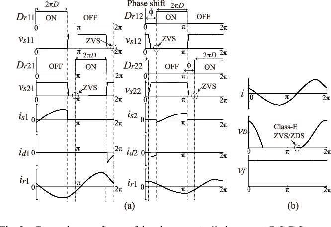
Figure 2 From Design Of A Dc Dc Converter With Phase Controlled Class D Zvs Inverter Semantic Scholar
The purpose of this paper is to propose applying thinned-out method to a conventional class E rectifier and improve the low output regulation.
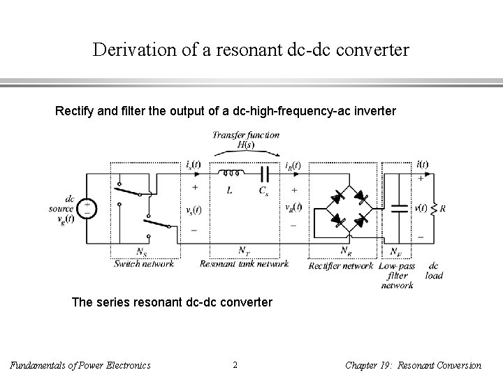
Resonant dc/dc converter with class-e inverter and class-e rectifier. And both types have nonzero power loss in the on-state resistance of the active switch. A new type of high-frequency high-efficiency resonant DCDC converter is proposed analyzed and verified experimentally. Fundamental Theory and Applications 48 1 123-126.
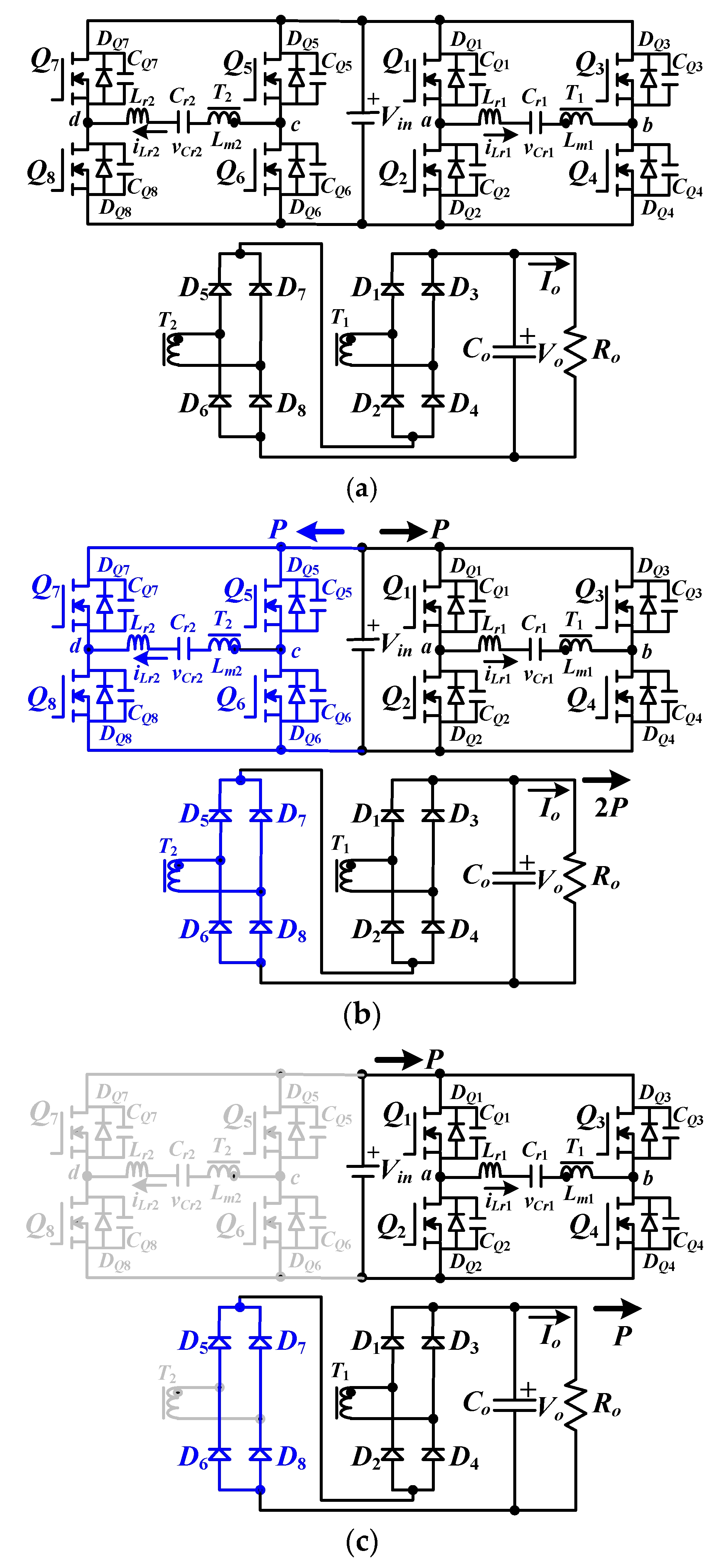
A new control method of a resonant DCDC power converter with a Class DE inverter and Class E rectifier is proposed. A new control method of resonant DCDC converter with Class DE inverter and Class E rectifier is proposed which can easily regulate the output voltage for both wide load and line variations while. IEEE Transactions on Circuits and Systems I.
A new control method of resonant dcdc converter with Class DE inverter and Class E rectifier is proposed. Both types have nonzero power loss in the on-state resistance of the active switch. The second harmonic resonant Class E inverter has no RF choke and has small power dissipation in.
The resonant dcdc converter with the Class DE inverter and Class E rectifier using the thinned-out method. Another advantage of thinned-out method is that it can operate with low noise and simple systems. It has been applied to DCDC converters as high-density power sources.
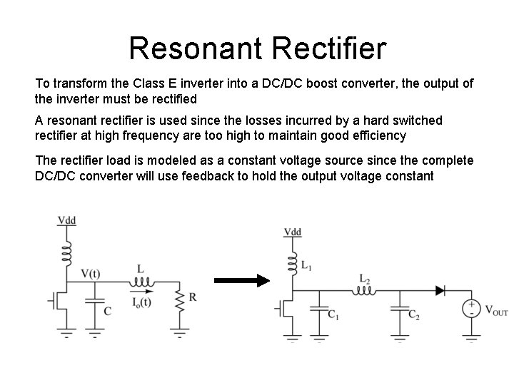
ZVS-Class E inverters need an RF choke and ZCS-types have the turn-on switching loss increasing with operating frequency. Class E amplifiers have used as inverters for highly efficient dcac energy conversion. When the class-E rectifier controlled by this method is used in a class-E DCDC power converter both the inverter and rectifier operate under zero-voltage-switching conditions.
Class E switching conditions are achieved for both the inverter and rectifier. ZVS-Class E inverters need an RF choke and ZCS-types have the turn-on switching loss increasing with operating frequency. Class E amplifiers have been used as inverters for highly efficient DCAC energy conversion.
The proposed circuit partially absorbs the secondary-side compensation resonance inductance into the equivalent inductance of the Class-E ZCS rectifier. Class E switching conditions are achieved for both the inverter and rectifier. In this paper we propose to combine the.
Conventional converters with the class DE inverter are controlled by varying the operating frequency the switch duty ratio or the phase difference with two. It consists of a Class DE inverter and a Class E rectifier. The proposed circuit is composed of phase-controlled Class-DE inverter and Class-E rectifier.
Some experimental results are shown as a class E 2 resonant dcdc converter. The purpose of this paper is to propose the application of the thinned-out method to a conventional class E rectifier and improve the low output regulation. Resonant dcdc converter with class DE inverter and class E rectifier using thinned-out method deleting some of the pulses to the rectifier.
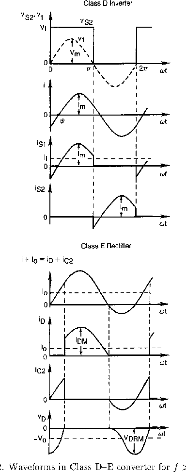
A new resonant dcdc converter is introduced along with its analysis and experimental results. It consists of a Class D resonant inverter and a Class E rectifier. The dcdc converters output power is controlled in the rectifier by eliminating its diode-voltage pulse at a desirable rate.
As a remedy to these problems we propose to combine the Class DE inverter with the Class E rectifier using the thinned-out method deleting some of the pulses to the rectifier. The class-E rectifier acts as an impedance inverter and is compatible with the class-E inverter. Therefore the efficiency of the converter is very high at switching frequencies in the megahertz range.
One can easily regulate the output voltage or power with eliminating the diode. An analysis leading to design equations is carried out. In this paper a phase control scheme for Class-DE-E dc-dc converter is proposed and its performance is clarified.
We can easily regulate the output voltage or power with eliminating the diode voltage pulse on the rectifier at a constant rate while the operating frequency is fixed. A new resonant dcdc converter is proposed. The class DE inverter offers high-efficiency power conversion under high operating frequency megahertz order with low switching noises and low switch voltage stress.
It consists of a Class DE inverter and a Class E rectifier. As the other advantages of thinned-out method it can operate with low noises and simple systems. It is called a class-E converter because it consists of a class-E inverter and a class-E rectifier.
The Class D inverter ensures a low peak voltage across the transistors and the Class E rectifier offers low switching losses and noise. Some experimental results are shown as a class Esup 2 resonant DCDC power converter. The proposed circuit achieves the fixed frequency control without frequency harmonics lower than the switching frequency.
Consequently the converter can operate with load resistances from a full. Moreover it is possible to achieve the continuous control in a.
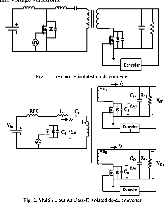
Figure 1 From Multiple Output Class E Isolated Dc Dc Converter Semantic Scholar
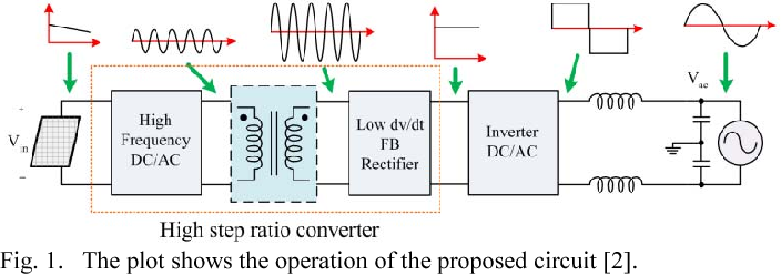
High Step Up Ratio Dc Dc Converter Using Class E Resonant Inverter And Class De Rectifier For Low Voltage Dc Sources Semantic Scholar
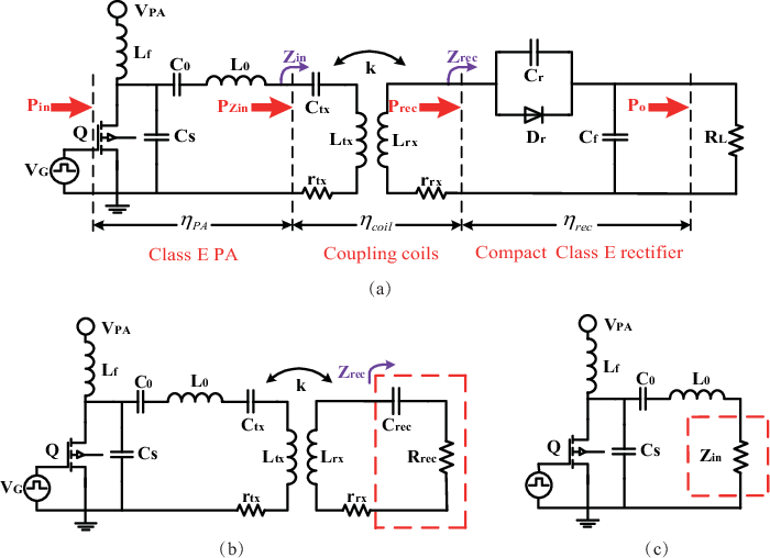
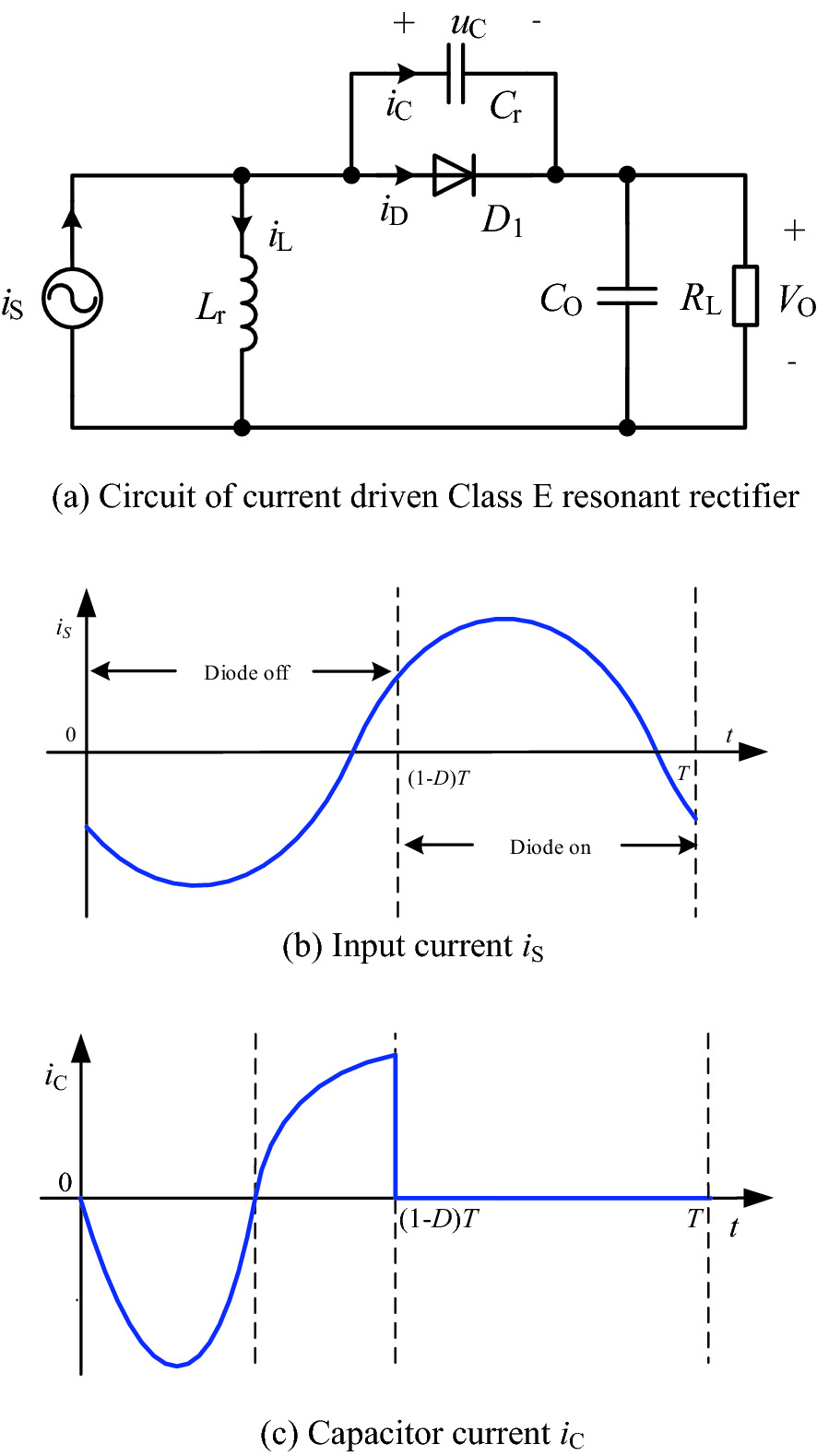
Pdf Design Procedure Of A Class E2 Dc Dc Converter For Megahertz Wireless Power Transfer Based On A Compact Class E Current Driven Rectifier Semantic Scholar

Classification Of The Dc Dc Converters Download Scientific Diagram

Resonant Boost Converter Design Justin Burkhart April 15
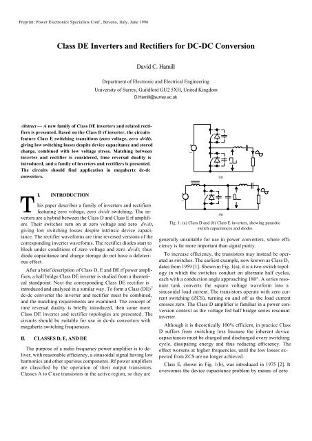
Class De Inverters And Rectifiers For Dc Dc Hamill And Hamill

Classification Of The Dc Dc Converters Download Scientific Diagram
Resonant Rectifier In Multi Mhz Dc Dc Converter Springerlink
Upcoming Assignments Preparation For Lecture 2 Read Section
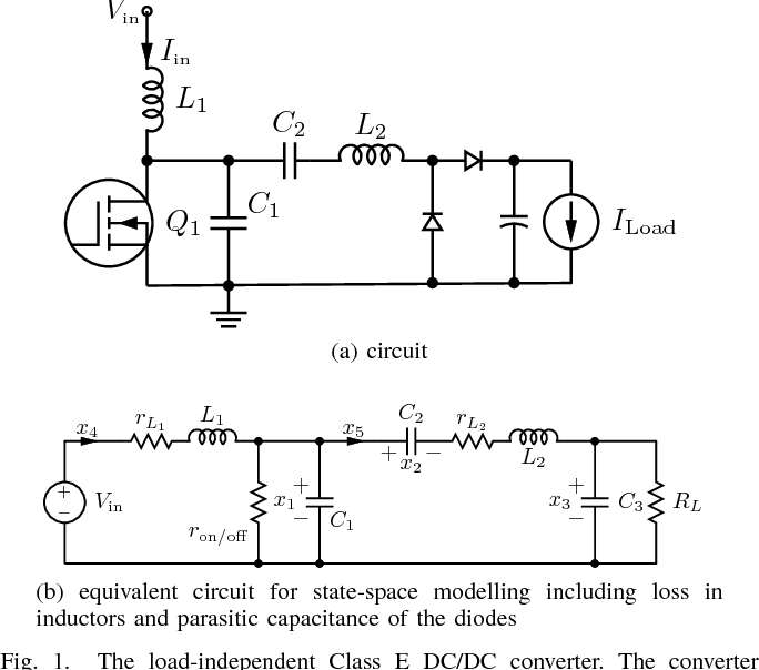
Sate Space Modelling And Design Of A 10mhz 180w Class E Dc Dc Converter Using Wbg Devices Semantic Scholar
Dc Dc Converter With Class D Inverter And Class E Rectifier Semantic Scholar

Dc Dc Converter With Class D Inverter And Class E Rectifier Semantic Scholar
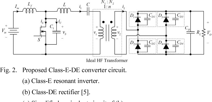
Figure 2 From High Step Up Ratio Dc Dc Converter Using Class E Resonant Inverter And Class De Rectifier For Low Voltage Dc Sources Semantic Scholar

The Resonant Dc Dc Converter With The Class De Inverter And Class E Download Scientific Diagram
Energies Free Full Text Implementation Of A Parallel Series Resonant Converter With Wide Input Voltage Range Html

Resonant Boost Converter Design Justin Burkhart April 15

Multiple Output Class E Isolated Dc Dc Converter Download Scientific Diagram
Resonant Boost Converter Design Justin Burkhart April 15

Figure 1 From Push Pull Zero Voltage Switching Resonant Dc Dc Converter Based On Half Bridge Class De Rectifier Semantic Scholar
Post a Comment for "Resonant Dc/dc Converter With Class-e Inverter And Class-e Rectifier"