How Does A Frequency Converter Work
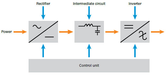
Static frequency converter is changing fixed grid power through AC to DC to AC by inner electronic parts and components the multifunctional inverter converts the mains 50 Hertz or 60 Hertz 120V 240V 400V through conversion circuit and transforms into the required voltage and frequency power source the output power source can simulate international power system standards. First it converts ac to dc then secondly dc to ac of desired frequency.
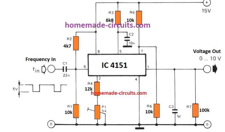
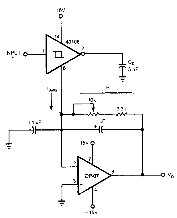
3 Frequency To Voltage Converter Circuits Explained Homemade Circuit Projects
How frequency converter works.
How does a frequency converter work. Most frequency converters offer the user the ability to set motor speed manually via a multi-position switch or keypad or use sensors pressure flow temperature level etc to automate the process. With that knowledge we can go through the working of the boost converter step by step. The easiest way to cure this problem is to raise an obstacle for the current.
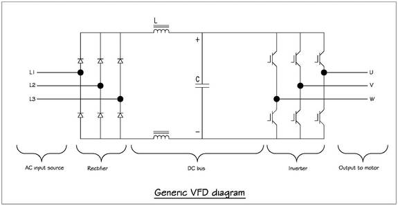
VFD is shorted for Variable Frequency Drive also known as AC Drives and Inverters -- thats used to make an AC motor working in variable speed among other parametersThis is definition used in all topical discussion on this paper. A frequency converter at its most basic is a device used to change another devices frequency. An electronic frequency converter is sometimes called a solid-state frequency converter.
A frequency inverter is an electronic device which enables the conversion of an electrical variable current. For understanding how our frequency converter works one needs to understand the concept of frequency and its units. The frequency inverter also called an adjustable speed drive ASD or a variable frequency drive VFD is used to vary the speed power and torque of a connected induction motor to meet required load conditions.
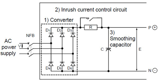
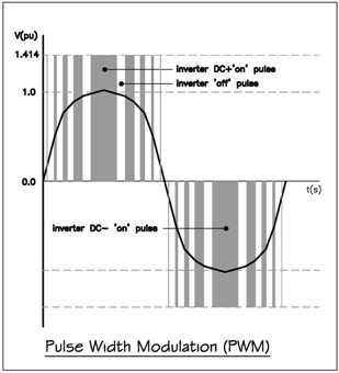
These can be electronically or electromechanically controlled. In this case the frequency inverter transforms an AC current with a certain fixed frequency into a voltage with variable amplitude and frequency. The converter is comprised of six diodes which are similar to check valves used in plumbing systems.
To change the frequency of ac current frequency converter goes through two stage conversion. To understand the working of a boost converter it is mandatory that you know how inductors MOSFETs diodes and capacitors work. Modern BUCs convert from the L band to K u band C band and K a band.
How does a Variable Frequency Drive work. I work with mobile generators so I know all the basic terms but I have no clue how this thing works. I work with a frequency converter that takes 60hz 120208 and turns it into 400hz 120208.
An electromechanical converter is usually used within motor-generator sets. You should now have a pretty good understanding of the workings of a frequency converter and how it controls the speed of a motor. Older BUCs convert from a 70 MHz intermediate frequency IF to K u band or C band.
A frequency inverter is often confused with a frequency converter since both appear to change output voltage frequency and amperage. A basic VFD system generally consists of an AC motor a controller and an operator interface. The frequency converter is also a energy saver and in many applications also noise limiter.
Other names for this are frequency converter AC drive converter etc. VFD for AC motors have been the innovation that has brought the. It converts a band of frequencies from a lower frequency to a higher frequency.
The controller can change the amount of time the IGBTs are open to increase or decrease the frequency and wave length to control the motors speed torque and direction and with a few additional control loops it can be used to exactly match the required loading to provide precise control of a system and unlock energy savings. Lets have a look at it. The switching technique of a modern frequency converter causes a zero-sequence current that under certain circumstances finds its way through the bearings.
The use of frequency converters will increase the probability of this type of bearing failure occurring. Describes the functioning of VFD or variable frequency drive. It might also be used in rotary sets.
Frequency converter is a calculating tool that allows you to convert a frequency value in its standard unit to its bigger and smaller units. The output capacitor is charged to the input voltage minus one diode drop. They allow current to flow in only one direction.
The direction shown by the arrow in the diode symbol. The first stage of a Variable Frequency AC Drive or VFD is the Converter. - Comments are welcome.
Https Www Powervision Eng Ch Profile Publications Pdf Hydrovision 2016 Nicolet Pdf

Frequency Converter Circuit
Variable Frequency Drive Basics Working Principle
2 Simple Voltage To Frequency Converter Circuits Explained Homemade Circuit Projects
Frequency To Voltage Converter Circuit Diagram

Frequency Converters Power Systems International

Variable Frequency Drives Explained Vfd Basics Igbt Inverter The Engineering Mindset

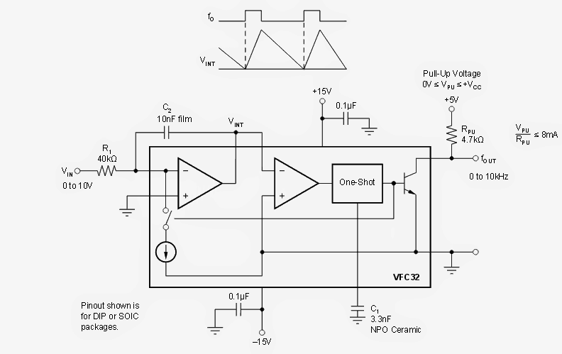
Voltage To Frequency Converter Circuit
What Is A Frequency Inverter
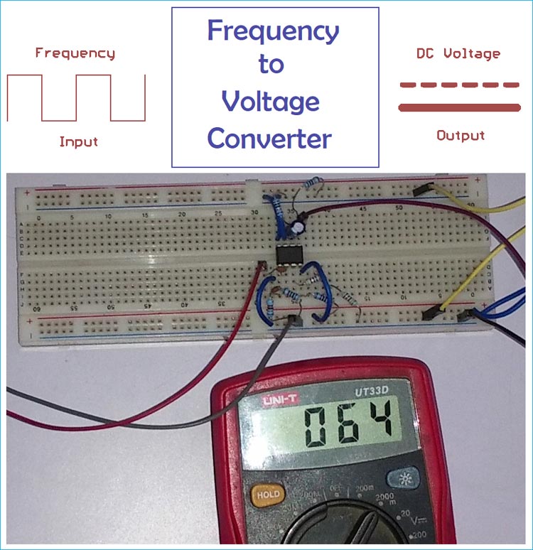
Frequency To Voltage Converter Circuit Diagram
What Is A Frequency Inverter

Single Phase Low Frequency Commutation Dc Ac Converter A Design Download Scientific Diagram
What Is A Static Solid State Frequency Converter Gohz Com

Variable Frequency Drive Working Principle
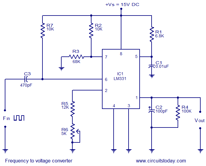
Frequency To Voltage Converter Using Lm331
Https Www Powervision Eng Ch Profile Publications Pdf Hydrovision 2016 Nicolet Pdf
2 Simple Voltage To Frequency Converter Circuits Explained Homemade Circuit Projects
2 Simple Voltage To Frequency Converter Circuits Explained Homemade Circuit Projects

Variable Frequency Drive Or Vfd Electrical4u
Post a Comment for "How Does A Frequency Converter Work"